Contents [hide]
- Stacking Technologies
- Aruba VSF Stacking Solutions and Platforms
- VSF Member Roles and Links
- VSF Open Virtual Switch Database (OVSDB)
- VSF Topologies
- VSF Requirements
- VSF Member ID and Port Numbers
- VSF Configuration Example
- VSF Pre-Provisioning
- Tracing Layer 2 Unicast Traffic
- VSF Failover and OPSF Graceful-restart
- VSF Link Failure
- Split Detection Using Multi-Active Detection (MAD)
Stacking Technologies
Operational Planes
A network device is logically composed of three operational planes, and each plane performs specific tasks.
1. Data Plane
This plane sends and receives frames using specialised hardware called Application Specific Integrated Circuits (ASIC).
2. Control Plane
This plane determines what to do with the data that has been received. These decisions include things like routing, switching, security and flow optimisation. Data and Control plane have a tight relationship to process any data as fast as possible.
3. Management Plane
This plane is used to configure and monitor the device. This is separate from the data plane for security and accessibility reasons. You do not want access to the device to be completely reliant on things like VLAN’s or VRF.
Introduction to Stacking Technologies
Stacking technology allows you to manage a group of devices as a single device, a virtual switch. Control and Management plane functions are centralised in one group member, but each member runs its own independent data plane.
Stacking benefits include:
- Ease of management: managing as one switch instead of multiple separate switches
- Network simplification: since multiple devices share a common control plane, routing protocols and Spanning Tree are no longer needed inside the stacking group.
Aruba switching supports two primary stacking technologies:
1. Virtual Switching Framework (VSF)
2. Virtual Switching Extension (VSX)
But this course is focused on VSF
Distributed Data Plane Distributed Link Aggregation
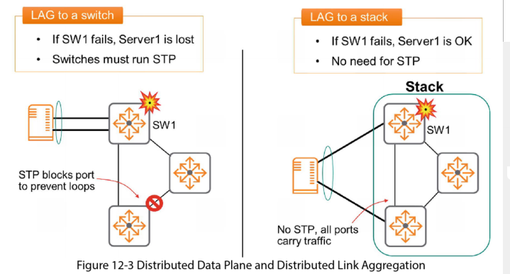
By connecting a server via a LAG connection to 2 different switches in a stack, if one switch fails the server can still send and receive traffic using the link to the other switch in the stack. There is no need for STP as the stack operates from a single control plane.
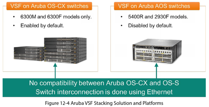
Aruba VSF Stacking Solutions and Platforms
You can configure a maximum of 10 members in a stack.
You cannot form a VSF stack between switches from different OS families.
VSF Member Roles and Links

VSF switches are interconnected using SFP56 ports. When you configure port for VSF it can no longer be used as a Layer 2 or 3 interface. In other words the port does not belong to the switches Data plane.
VSF Open Virtual Switch Database (OVSDB)
The OVSDB runs in the Master switch and contains state and configuration data for the VSF Stack itself. The Master switch syncs the OVSDB content with the Standby to ensure it can quickly take over the Master role without interruption.
The OVSB includes 6 tables:
- VSF Member table
- VSF link table
- System table: includes the number for members, MAD (Multi-Active Detection – see section further down for more info) status, fragment status, and topology type
- Subsystem table: boot time for each member
- Interface table
- Topology table
VSF Topologies
Daisy Chain
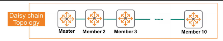
- Members are connected with a single link
- A switch or link failure causes the stack to be split
Ring Topology
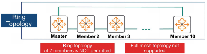
- This offers a backup path the case of a switch or link failure
- This is the recommended method
VSF Requirements
- Use AOS-CS version 10.4 or higher
- All members must run the same OS-CX version
- Only 6300 switch models can form the stack, but model combination is allowed
- A single link is only allowed for VSF link
- VSF link uses regular Ethernet port
- Max 10 members per stack
VSF Member ID and Port Numbers

VSF Configuration Example

VSF Pre-Provisioning
This allows you to prepare the VSF link and member for a specific 6300 switch before the switch is connected to the stack. When it joins the stack it then boots up with the correct config.
Switch(config-VSF)# VSF member 4
Switch(config-VSF)# type jl658a
Switch(config-VSF)# link 1 1/1/25
Switch(config-VSF)# link 2 1/1/26
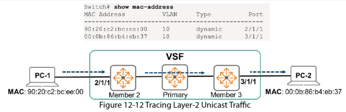
Tracing Layer 2 Unicast Traffic
When a VSF member receives a frame for L2 forwarding it consults the L2 forwarding table to determine the egress interface. If the egress interface is on another member, the source member forwards the packet on the VSF link.
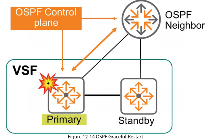
VSF Failover and OPSF Graceful-restart
The Primary member is the most important in the stack: it runs the control and management planes. External devices exchange routing and switching protocols directly with this member. If this fails, and you don’t have a secondary member, the stack dies.
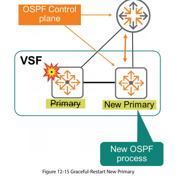
If you do have a Secondary member, this becomes the new master and takes over all the Masters roles.
In the case of a failure and the Secondary becoming the Master, OSPF notifies peers of the event. This triggers a rebuild of OSPF adjacencies. During the convergence the switch continues to route traffic based on the last known routing information. This typically only lasts a few seconds. After OSPF is fully operational routing uses the new information.
VSF Link Failure
This could cause a fragmented stack.
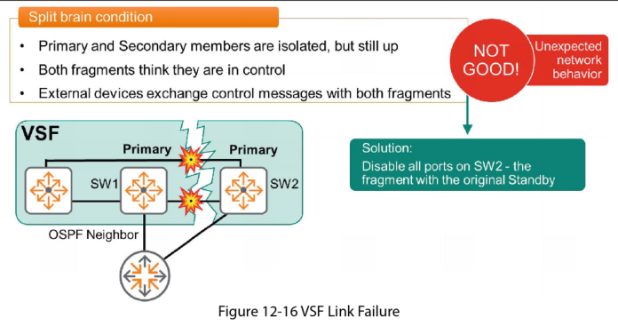
In this example SW1 was primary and SW2 was secondary. After the link fails between the members, SW1 continues to think it’s the Primary but Sw2 also thinks it’s the Primary as it cant communicate with SW1. This is known as a Split-brain condition.
Split-brain can cause unexpected network behaviour. A packet received in one fragment and destined for the other is discarded. Both segments use the same IP address and the same routing information which can cause very strange network behaviour.
The best way to solve split brain is to disable the ports of one of the segments.
Split Detection Using Multi-Active Detection (MAD)
Using MAD, if a VSF link failure occurs the Standby member verifies the primary member status first using another method before it becomes the primary. If the original Primary is up then all members, that are not the primary, will disable all their ports.
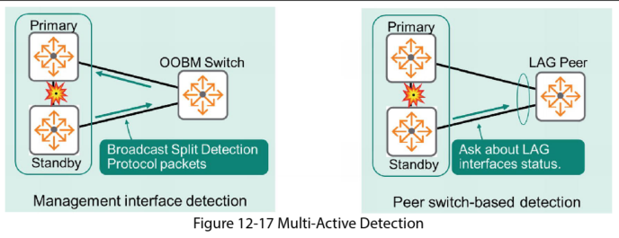
VSF uses 2 mechanisms to verify the status of the Primary member:
1. Management Interface Split Detection
In this method you connect Out-Of-Band Management (OOBM) interfaces to primary and secondary stack members. These interfaces must be in the same Layer-2 broadcast domain (VLAN). Each member broadcasts Split Detection Protocol Packets to identify stack fragments that are currently operational.
2. Peer Switch Based Detection
This method does not require additional connections and relies on the Link Aggregation Group (LAG) implementation. Switches ask the LAG Peer about its interface states using those interfaces connected to Primary and secondary stack fragments. If the LAG peer indicates its interfaces to the Primary member are up, the Standby member detects a Split-brain situations and shuts down its interfaces.