An endpoint may only have one DG (Default Gateway), and a single DG means a single point of failure.
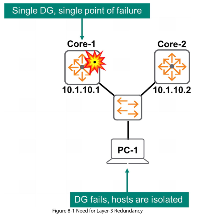
In this example, if Core-1 is the DG for PC-1 and Core-1 fails, PC-1 and any other endpoints using Core-1 as the DG will be isolated.
You could add another DG for redundancy, but you would have to somehow change the IP of the DG configured all the endpoints network configuration in the case of a failure (either manually for each end point or by reconfiguring the DHCP scope. This is not practical.
Contents [hide]
First Hop Redundancy Protocol (FHRP)
The solution to this issue is to use some kind of First Hop Routing Protocol. This uses a coordinated Gateway Solution which means there is no change to endpoint IP configuration.
FHRP creates a single coordinated gateway from two or more physical routers. They appear as a single device to the endpoints with a single Virtual IP address (VIP).
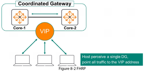
Normally, the Primary routing device serves the DG role, forwarding traffic for endpoints. The Secondary unit monitors the Primary device state. If the Primary fails the Secondary device takes over. From the endpoint perspective the VIP address is always available and there is no disruption to users.
Virtual Router Redundancy Protocol (VRRP)
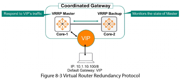
RFC 5798 defines the VRRP, a standard FHRP that enables two or more routing devices to provide gateway redundancy. VRRP uses a Master-Standby architecture, one gateway forwards traffic sent to the VIP address, while the other non-forwarding device is the backup.
VRRP Instances
AOS-CX allows you to deploy multiple instances of VRRP, often to balance the load for VLANs.
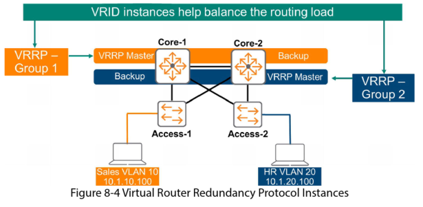
Each instance has a unique Virtual Router ID (VRID) which AOS-CX refers to as Group ID. In this example VRRP Group 1 serves VLAN 10 while VRRP Group 2 serves VLAN 20.
In this example both Core switches are being used as a Master and Standby for load balancing.
Core 1 is the Master for VLAN 10 with Core 2 as the Standby.
Core 2 is the Master for VLAN 20 with Core as 1 the Standby.
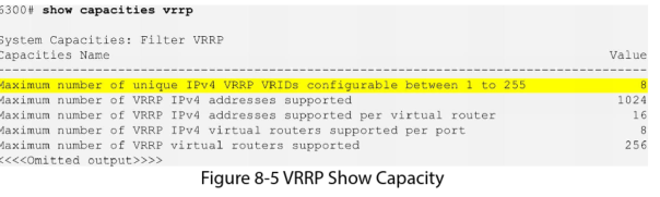
VRRP Instances Capacity
Instances in VVRP are also known as Virtual Router IDs (VRIDs), the number the switch supports depends on the switch type. You can verify this by using the show capacities VRRP command.
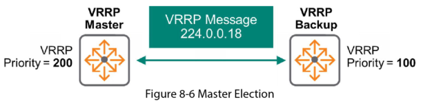
Master Election
VRRP members exchange multicast messages to elect the Master gateway using address 224.0.0.18, IP protocol number 112. To control the Master election you set a priority value from 1 to 255. The highest priority wins. If both devices have the same priority the gateway with the highest IP address wins the election. The default priority is set to 100.
Virtual IP Address
You assign a unique “real” IP address to each individual gateway, then a unique IP for the VIP address. Each VRRP instance must also have a unique IP address.
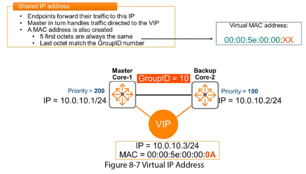
A Virtual MAC address (vMAC) is automatically assigned to the VIP. This MAC is:
– 00:00:5e:00:00:XX, where XX= the VRID (Group ID)
In the above example the VRID = 10, so the vMAC is:
– 00:00:5e:00:00:0A (in Hex A = 10 decimal)
When the endpoints ARP for the DG address of 10.0.10.3, they will learn the vMAC and add it to their ARP table.
VRRP Failover Operation
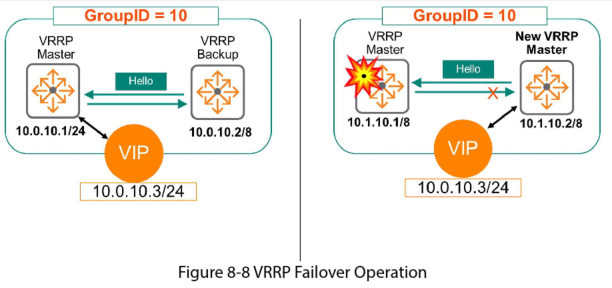
The Standby monitors the Master gateway via a keepalive mechanism. If the Master fails the standby stops receiving keepalive messages. The former Standby then takes over as the new VRRP Master and begins to froward traffic sent to VIP 10.10.10.3
VRRP Preemption
In the previous example, what happens when the switch on the left comes back online?
- If preemption is enabled this switch will resume its original role as the Master the switch on the right goes back to Standby. This can be useful in the cause of multiple VRRP instances where in the case of a failure, one switch could be carrying the load for all endpoints. Preemption is on by default
- If preemption is disabled, switch on the right remains the Master and the switch on the left remains the Standby. To disable preemption use the command: no prempt
VRRP and MSTP Coordination
When using VVRP and MSTP there must be coordination between the MSTP Root Bridge and the VRRP. Otherwise if there is a loop there could be some unexpected behaviours.
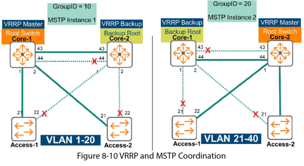
In figure 8-10, Core 1 is configure as the Root Bridge for MSTP 1 which supports VLANs 1-20. Core 1 is also the VRRP Master for the same VLAN range. If Core 1 fails, Core 2 becomes the new MSTP Root Bridge for instance 1 and the new VVRP Master. Both L2 and L3 protocols are coordinated, L2 STP uses the same forwarding path as L3 Routing.
Configuring VRRP
On Core switch 1
On int VLAN 1111 create the VRRP routing process using Group 1
Interface vlan 1111
VRRP 11 address-family ipv4
Define 10.11.11.254 as the virtual IP address then enable the group
Address 10.11.11.254 primary
No shutdown
exit
Display the VRRP information
Show VRRP in vlan 1111
You must then configure core switch 2
conf
Interface vlan 1111
VRRP 11 address-family ipv4
Address 10.11.11.254 primary
No shutdown
Priority 254
Exit
As we set the higher priority on Core 2 it will become the master.