OPFv2 Router ID and Messaging
OSPFv2 is the most popular option for corporations to route traffic within their networks.
OSPF Introduction

OSPF does not use UDP or TCP. OSPF advertisements are placed directly in an IP packet, therefore it does not have a TCP or UDP port number. It has IP protocol number 89.
NOTE: The IP protocol number is a number associated to that protocol that is in use in Layer 4. It is included as a field in the L3 header. The announcement in L3 helps network devices to be aware of the L4 protocol that is in use without decapsulating the packet. TCP uses protocol number 6 and UDP used protocol number 7.
Router ID Overview and Selection Criteria
All OSFP routers require a unique Router Identifier (RID). This is a 32 bit IP address in dotted decimal notation. Routers send this ID in all their OSPF packets. Routers can automatically assign their own RID or you can do it manually. Manual is recommended for ease of management and troubleshooting.
Process for assigning ID in AOS-CX:
1. If you manually specify the RID then that is what it uses
2. If not, the loopback interface with the highest IP address becomes the RID
If no loopback interfaces exist, the regular interface with the highest IP address becomes the RID. Non-functional interfaces in a down state are not considered.
Loopback Interface
By default, each switch has an internal loopback interface (lo0) with the IP address 127.0.0.1. This IP address is used only for internal traffic transmitted within the switch and is not used in packet headers in egress traffic sent to network devices.
You can configure up to seven other loopback interfaces (lo1, lo2, lo3, and so on) on the switch to use to transmit network across the network. Each loopback interface can have multiple IP addresses. Routing protocols, such as RIP and OSPF, advertise the configured loopback addresses throughout a network or autonomous system.
User-defined loopback addresses provide the following benefits:
- A loopback interface is a virtual interface that is always up and reachable as long as at least one of the IP interfaces on the switch is operational. As a result, a loopback interface is useful for debugging tasks since its IP address can always be pinged if any other switch interface is up.
- You can use a loopback interface to establish a Telnet session, ping the switch, and access the switch through SNMP, SSH, and HTTP (WebAgent).
- A loopback IP address can be used by routing protocols. For example, you can configure the loopback IP address as the router ID used to identify the switch in an OSPF area. Because the loopback interface is always up, you ensure that the switch’s router ID remains constant and that the OSPF network is protected from changes caused by downed interface.
OSPF General Operation Overview
Phase 1: Build a neighbour Table
Directly connected OSPF neighbours introduce themselves to one another. They do this by sending OSPF Hello packets out each OSPF interface. If the parameters match the routers form an OSPF neighbour relationship.

Phase 2: Build a Topology database
The topology database is also called a link state database (LSDB). This is where routers share known subnets with other routers. The objective is to build a database of every single link (subnet), every single router, and how those routers and subnets are interconnected. They do this by sending multicast Link State Advertisements (LSAs).
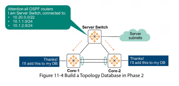
Once every router has received LSAs from every other router, the routers have a full topology database. Each router has an identical topology database.
NOTE: routers advertise the entire contents of their topology database to other routers. This includes what they have learned from other routers, not just what is directly connected to them.
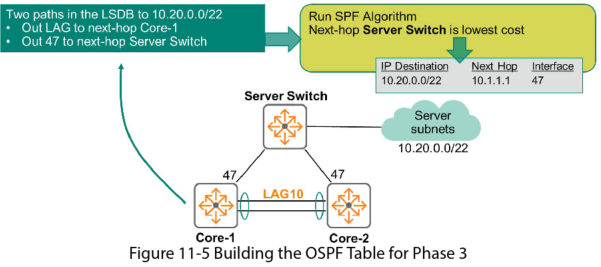
Phase 3: Build the OSPF Table
In this phase the router builds the best paths for each destination. It does this by running the SPF (Dijkstra) algorithm on the topology database.
Phase 4: Build a routing Table
This phase publishes the best paths (discovered in Phase 3) to the routing table (FIB).
OSPFv2 Neighbours
Hello Messages
- Directly connected OSPF routers send hello packets to ensure 2 way communication and detect any failures
- By default these are sent every 10 seconds
- They are sent to multicast address 224.0.0.5, this is a reserved “attention all OSPF routers” multicast address
Hello packets are used to build a neighbour table. Routers form a neighbour relationship if they are compatible. They must have the:
- Same subnet and subnet mask
- Same area and area type
- Same timers (e.g.: 10 seconds)
- Same authentication type
To verify the hello interval you can use the command: sh IP OSPF neighbor detail
OSPF Neighbour States
OSPF uses a Finite State Machine (FSM) to process neighbour state transitions between routers when certain conditions are satisfied. This is divided into 2 phases:
1. Establish Neighbour Adjacencies
- Both routers start in the DOWN neighbour state
- Core 1 goes to INIT state and sends the first Hello message
- Core 2 received the Hello message and response, indicating that the message as been seen and values are compatible. Core 2 goes to INIT state
- Core 1 receives the Hello message and goes to the 2-WAY state. It sends Hello message again but this time includes both Router IDs
- Core 2 receives this message and moves to the 2-WAY state
2. Synchronise OSPF Database
In this example Core 1 and Core 2 are the only routers in the network so they continue to the database synchronisation process:
- Core 1 initiates the sync by sending a Database Description packet. It transits to the EXSTART neighbour state
- Core 2 sends a Database Description packet. It transits to the EXSTART neighbour state
- The goal of the EXSTART is to see which router will become the MASTER
- Core 2 sends another Database Description packet and moves to the EXCHANGE state. Core 2 is now sharing the contents of its LSDB
- Core 1 sends another Database Description packet and moves to the EXCHANGE state. Core 1 is now sharing the contents of its LSDB
- after several packets each router will have copy of the others LSDB
- Core 1 and Core 2 move to the FULL state when there is no more information to be exchanged
You can verify the state by using the command show IP OSPF neighbors
OSPFv2 Operations
OSPF Network Types
2 options exist for network types
- Point to Point Networks: only 2 peers are on the link. Recommended to set to this if you only have 2 routers
- Broadcast networks: two ore more peers on the link. This is the default mode
To verify the type of network use the command: show IP OSPF interface
Broadcast Network Scalable Problem
In a large Broadcast Network type with lots of routers, the routers could be sending hundreds or thousands of routes for each OSPF peer. This could impact performance of the routers.
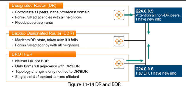
To solve this scalability challenge, OSPF uses a Designated Router (DR) in the broadcast domain. This router maintains a full neighbour state of each device, however, the non-designated routers do not exchange database information with each other.
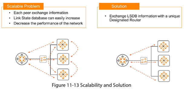
To maintain high availability you can elect a Backup Designated Router (BDR) to avoid a single point of failure. This maintains a full database of each router but only advertises information when the primary DR is no longer available.
Designated Router Election
DR and BDR is based on priority value assigned to an interface, the highest priority wins the election. In the case of a tie the router with the higher router ID becomes the DR.
- Priority values can be between 0-255
- Default value is 1
- 0 means the router will not participate in router election
To set the priority value:
Interface <interface-id>
IP OSPF priority <priory-value>
To verify the priority value use the command:
Show IP OSPF interface
Or
Show IP OSPF neighbors
OSPF Area
In OSFP every router sends LSAa that advertise the entire contents of their LSDB to every other router. With hundreds of thousands of routers this can consume considerable bandwidth and the topology database can grow very large which consumes memory and CPU cycles on the routers.
To fix this issue we split the network into Areas.
An area is a group of OSPF routers that share the same Link State database. All routers must be part of an area.
When you split a large network in separate areas it has the following advantages:
- Reduce LSDB size
- Lower CPU utilisation
- Increased overall network stability
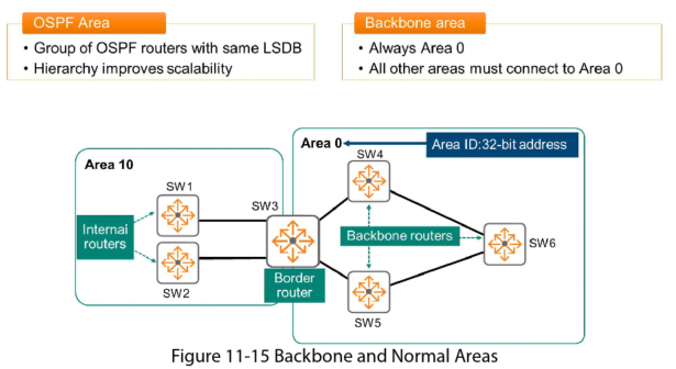
Normal Areas
In Figure 11-15, SW1 and SW2 are “Internal routers”. All their interfaces are in a single area. If they need to route outside their area they forward the packets to the Area Border Router (ABR). In this case the ABR is SW3. It has an interface in Area 10 and Area 0.
All normal areas must connect to area 0 as they cannot communicate directly with other areas without going through area 0.
Backbone Areas
Routers with interfaces in Area 0 are called backbone routers. If routers only have an interface in area 0 (SW4,5,6) they are called “Internal Backbone Routers”.
You assign interfaces to an area by assigning them to an area ID
This course focuses only on single-area designs in which all router interfaces are in Area 0.
OSPF LSA Type 1
OSPF routers generate different types of Link State Advertisements (LSAs) each with a different purpose.
Type 1 Overview:
- Router LSA
- All routers announce their existence and functional interfaces
- Generated by all routers in the area
- Scope: area wide
- Link Data depends on the Link Type
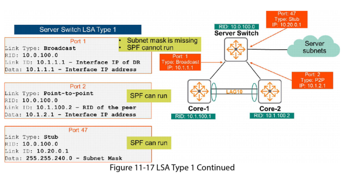
LSA Type 1 are for routers to announce themselves. They say “Hi, I am RID 10.1.100.1, and I have 3 different interfaces that are functional and are participating in this area”.
Link Types
Stub Link: used when OSPF is enabled on an interface and no OSPF neighbour exists on the interface. EG: loopback interface
Transit link: Used in a broadcast network with 2 or more OSPF neighbours
Point-to-Point link: Used in point-to-point networks, only one OSPF neighbour is expected on the link
You can verify the link type information by using the command:
Show IP OSPF LSDB
The image shows an example output from this command for different link types:
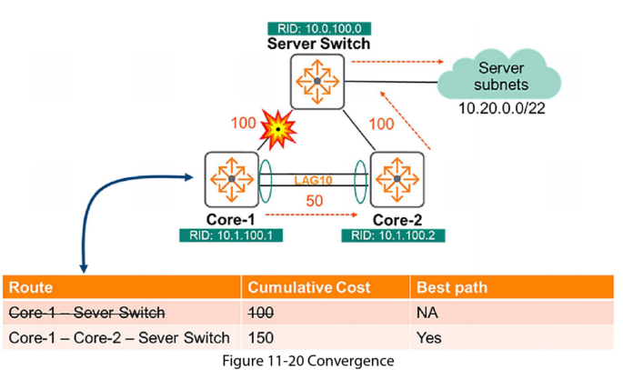
Path Selection
After all routers have successfully exchanged LSAa, they all have an identical LSDB. Now the routers run the Shortest Path First (SPF) (Dijkstras algorithm) to find the best paths to each destination subnet. The best path is the one with the lowest cost, and the cost is based on bandwidth.
Cost for each interface is calculated using the formula:
![]()
AOS-CX uses a default reference value of 100000 Mbps.
Configuring Cost Value
You can modify the cost of an interface in two different ways:
1. Modifying the reference bandwidth. This applies to the entire OSPF process which means it will affect all interfaces. To do this:
conf
router OSPF <process id>
reference-bandwidth <1-4000000>
2. Modifying the cost associated with a single interface:
conf
interface <interface id>
IP OSPF cost <Cost value>

OSPF Convergence
There are 2 components to OSPF routing convergence:
- Detect topology changes
This happens in 2 ways:
– a failure or change of status on the physical interface.
– a timeout of the OSPF hello timer. A neighbour is deemed dead if the wait time for the hello packet exceeds the dead timer. The default dead timer is four times the value of the hello timer. The default hello timer is 10 seconds. - Recalculate routes
When a change is detected an LSA is sent to all routers in the OSPF area to signal the change. The routers then re-run the SPF algorithm to calculate their new best paths
Passive Interface
When an interface is set as passive it will not send or accept OSPF packets on that interface. This might be used for an interface that only connects to a subnet with hosts, not other routers.
To set an interface as passive:
Conf
Int <interface-id>
IP ospf passive